void mbTCPtoEVB(uint8_t sn)
{
    if (MBtcp2evbFrame() != 0)                         // Frame received complete
    {
        if (pucASCIIBufferCur[0] == 0x01)              // Check whether the device address is 0x01
        {
            if ((uint8_t)pucASCIIBufferCur[1] == 0x05) // Write to a single device
            {
                if ((uint8_t)pucASCIIBufferCur[4] == 0xff)
                {
                    set_led_status(0);                 /* ON: 板载LED低电平点亮,set(0)=ResetBits=点亮 */
                    printf("LED ON\r\n");
                }
                else if ((uint8_t)pucASCIIBufferCur[4] == 0x00)
                {
                    set_led_status(1);                 /* OFF: set(1)=SetBits=熄灭 */
                    printf("LED OFF\r\n");
                }
                send(sn, recv_data, recv_len);
            }
            else if ((uint8_t)pucASCIIBufferCur[1] == 0x01) // Read Write to a single device
            {
                if (recv_data[recv_len - 1] != 0x01)
                {
                    printf("len error!%x\r\n", recv_data[recv_len - 1]);
                }
                else
                {
                    printf("Read OK!\r\n");
                    send_data[0] = recv_data[0];
                    send_data[1] = recv_data[1];
                    send_data[2] = recv_data[2];
                    send_data[3] = recv_data[3];
                    send_data[4] = 0x00;
                    send_data[5] = 0x04;
                    send_data[6] = 0x01;
                    send_data[7] = 0x01;
                    send_data[8] = 0x01;
                    send_data[9] = ~get_led_status();   /* 取反:低电平点亮语义 → Modbus 标准语义 */
                    send_len     = 10;
                    send(sn, send_data, send_len);
                    memset(send_data, 0, send_len);
                }
            }
            else
            {
                printf("error code!\r\n");
            }
        }
        else
        {
            printf("address error!\r\n");
        }
    }
}
报文处理逻辑
本例程中,从机地址设为 0x01。功能码 0x05 用于写单线圈(控制 LED 开关),数据为 0xff 时点亮 LED,为 0x00 时熄灭 LED;功能码 0x01 用于读线圈状态,回复当前 LED 状态。设备地址或功能码不匹配时会打印相应的错误信息。读 LED 状态时返回 ~get_led_status(),因为板载 LED 是低电平点亮,get_led_status() 返回的是 GPIO 电平(0=点亮, 1=熄灭),需要按位取反才能转换成 Modbus 标准线圈语义(1=ON, 0=OFF)。
运行验证
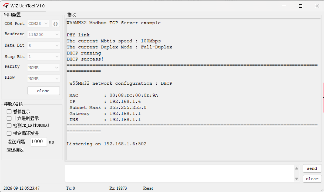
打开 WIZ UartTool V1.0,连接 DEBUG USB 对应 COM 口(115200 / 8N1)。烧录例程运行后,首先可以看到进行了 PHY 链路检测,然后打印了设置的网络地址信息,然后开始监听地址和端口号。预期串口输出如下:
W55MH32 Modbus TCP Server example
PHY link
The current Mbtis speed : 100Mbps
The current Duplex Mode : Full-Duplex
DHCP running
DHCP success!
====================================================================================================
 W55MH32 network configuration : DHCP

 MAC         : 00:08:DC:00:0E:9A
 IP          : 192.168.1.6
 Subnet Mask : 255.255.255.0
 Gateway     : 192.168.1.1
 DNS         : 192.168.1.1
====================================================================================================

Listening on 192.168.1.6:502
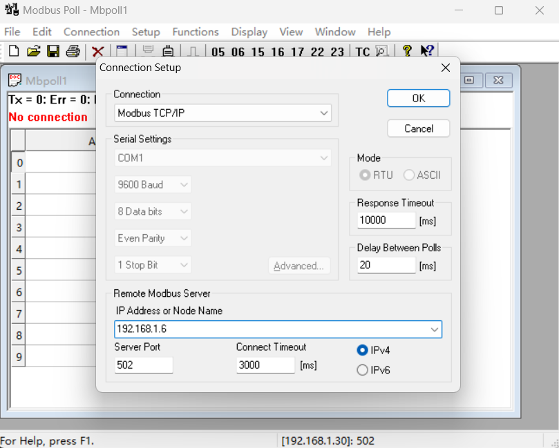
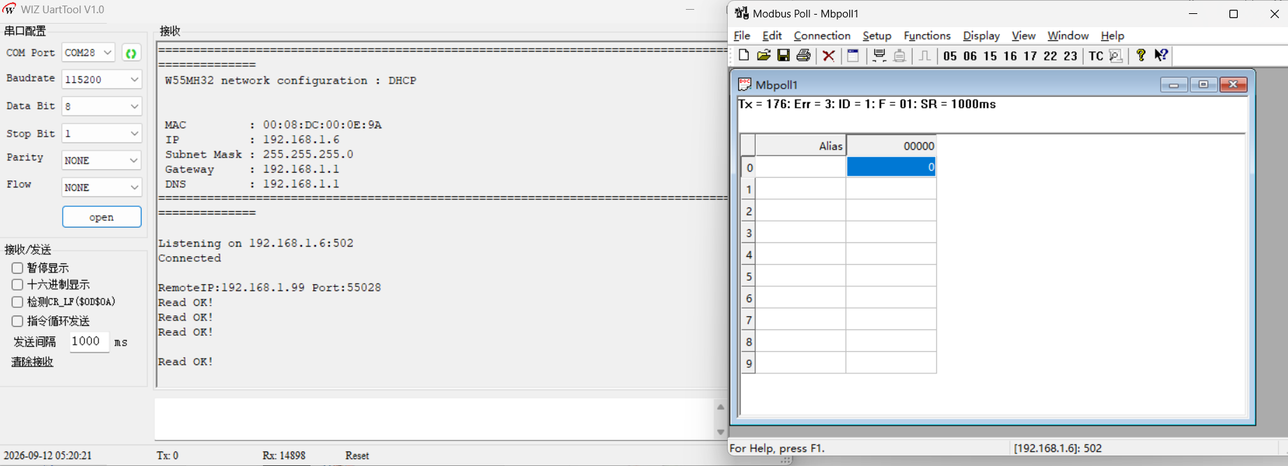
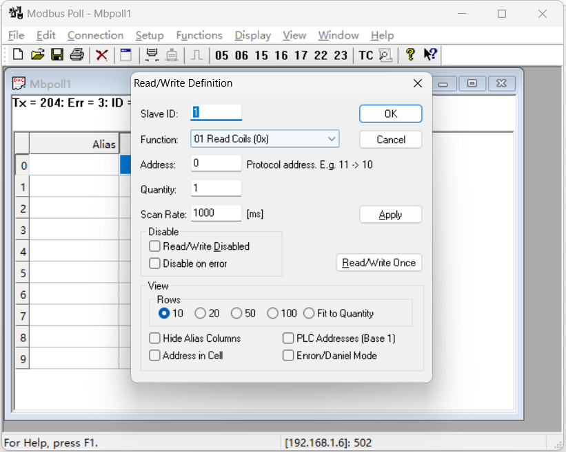
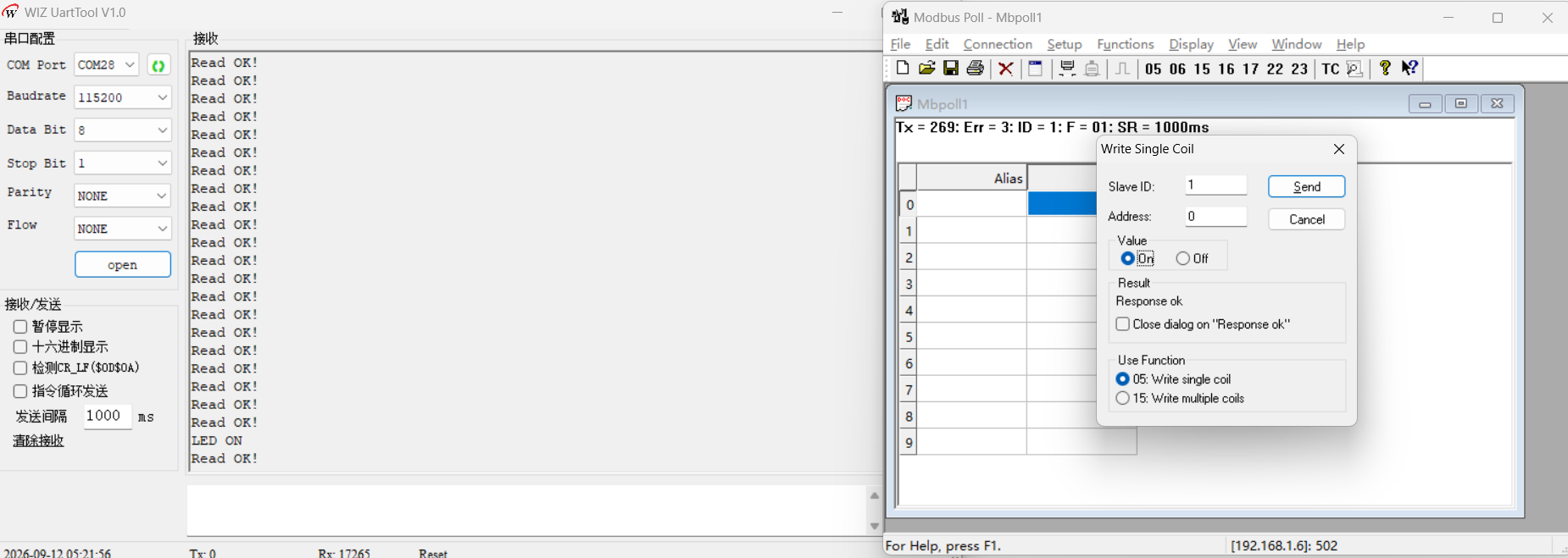
接着使用 Modbus Poll 工具进行 Modbus 测试:首先按 F3 设置连接服务器参数(Remote IP 填写 W55MH32 的 IP 192.168.1.30,Port 502,Slave ID 1);接着按 F8 设置读取参数(Function 01 Read Coils,Address 0,Quantity 1)并开启读取轮询,可以看到在不断读取 LED 状态;设置 LED 的状态为打开,可以看到 LED 成功打开,并且读取的 LED 状态已经更新。